Deleted
Deleted Member
Join Date: Apr 26, 2024 11:52:39 GMT
Posts: 0
Likes:
Last Online: Apr 26, 2024 11:52:39 GMT
|
Post by Deleted on Mar 15, 2017 2:51:50 GMT
|
|
Deleted
Deleted Member
Join Date: Apr 26, 2024 11:52:39 GMT
Posts: 0
Likes:
Last Online: Apr 26, 2024 11:52:39 GMT
|
Post by Deleted on Mar 15, 2017 3:19:56 GMT
|
|
Deleted
Deleted Member
Join Date: Apr 26, 2024 11:52:39 GMT
Posts: 0
Likes:
Last Online: Apr 26, 2024 11:52:39 GMT
|
Post by Deleted on Mar 15, 2017 11:29:28 GMT
|
|
Deleted
Deleted Member
Join Date: Apr 26, 2024 11:52:39 GMT
Posts: 0
Likes:
Last Online: Apr 26, 2024 11:52:39 GMT
|
Post by Deleted on Mar 16, 2017 7:11:57 GMT
|
|
Deleted
Deleted Member
Join Date: Apr 26, 2024 11:52:39 GMT
Posts: 0
Likes:
Last Online: Apr 26, 2024 11:52:39 GMT
|
Post by Deleted on Mar 19, 2017 0:09:35 GMT
So far, I was only talking about my firmware and OS, but now I have something to show. After days of messing around with lots of errors caused by both the very incomplete and incorrect documentation and my own mistakes, I have a pretty little output into the serial port. My code now can speak words and it says "hello" to the world (traditionally) and to Avril!!1 It's indeed pretty exciting. I am really proud of it. It's a big achievement for the project. For your information: the code runs on bare metal, nothing is behind it, nothing, there is even no firmware, in fact the code by itself is a firmware. there is only ROM code hardcoded into the chip which starts the boot process, boots our code from an SD card and transfers control to our code. And as it is seen by the register values printed, it even doesn't initialize CPU PLL, APLL, it stays in its reset state at the moment our code is getting control over. Cool. The machine is mips creator ci20, the photo of which I posted earlier, here. What our code does, it turns the LED from red to blue, initializing for this its pin before, initilializes UART4 and its RxD and TxD pins (this is for the output), then prints hello strings and some PLL related registers. For this there is also a conversion function translating integers into number strings, numeric literals. Then at the end it prints goodbye string and calls halting instruction WAIT. Somehow, ROM code invokes us twice, that's why there is two prints. this is yet to be investigated. The text above my print is from linux which resides on NAND and I am using it for flashing the SD card with my binary. Then I shutdown it, it's seen in fact. And here is the screenshot of this process.  The code writes into the serial port and there is established connection with my PC on that port (by means of the UART-USB adapter), so my computer can receive the output and show it on the display as you can see. But you probably know what a serial port and terminal connection is.  So. IT WORKS!11  PS. edited resolution, for the screenshot to not look too small. |
|
Deleted
Deleted Member
Join Date: Apr 26, 2024 11:52:39 GMT
Posts: 0
Likes:
Last Online: Apr 26, 2024 11:52:39 GMT
|
Post by Deleted on Mar 21, 2017 0:54:11 GMT
|
|
Deleted
Deleted Member
Join Date: Apr 26, 2024 11:52:39 GMT
Posts: 0
Likes:
Last Online: Apr 26, 2024 11:52:39 GMT
|
Post by Deleted on Mar 21, 2017 23:44:30 GMT
now you could fry eggs on it. Those for eating. Within my project, today (yesterday already) I did opposite to overclocking, I have set up PLLs, it's magic hardware modules for making clocks run at crazy speeds of GHz'es, because oscillators give MHz's. There are 4 PLLs on the chip, I've initialized two - the one for CPU and L2 cache and second for DDR and buses (it's AHB buses). APLL now is used (instead of EXTCLK - external oscillator) for the CPU and L2 cache, and it runs at 1200 MHz. MPLL runs at 400 MHz and is used for DRAM and buses and peripherals. But also I set up dividers for the core components, so for example CPU runs at only 200 MHz and everything else at 100 MHz. Peripheral clock is at 50 MHz. Because it's enough for the FW! I don't want my tiny computer burnt out. It doesn't have even a passive heatsink. It's a hardcore part of the initialization, and happily it works. After some stupid mistakes made of course. Now we are straight before SDRAM initialization process. But before, I have such a crazy idea to initialize the interrupt controller and timer, to do waiting a sane way. DRAM init needs a lot of waiting and it's about 400ms, so busy wait isn't good. The real sleeping, halting is. For this, we should configure the interrupt controller and supply a handler to handle the interrupt from the timer, OS timer. it's called here. After this most complex part of starting code, we will move on to the UEFI core (Dxe) deployment. |
|
Deleted
Deleted Member
Join Date: Apr 26, 2024 11:52:39 GMT
Posts: 0
Likes:
Last Online: Apr 26, 2024 11:52:39 GMT
|
Post by Deleted on Apr 1, 2017 5:58:26 GMT
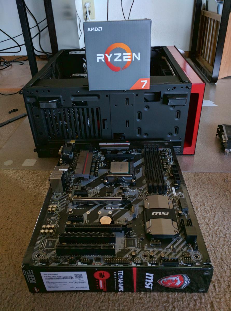
Just finished re-managing the cables. I don't need to struggle putting the back side panel back on anymore 😂😂😂  😛😛😛  |
|
332
Member
 Banned
Join Date: Sept 22, 2016 23:46:35 GMT
Posts: 176 
Likes: 39
Last Online: Apr 2, 2017 19:03:47 GMT
|
Post by 332 on Apr 1, 2017 6:36:58 GMT
So far, I was only talking about my firmware and OS, but now I have something to show. After days of messing around with lots of errors caused by both the very incomplete and incorrect documentation and my own mistakes, I have a pretty little output into the serial port. My code now can speak words and it says "hello" to the world (traditionally) and to Avril!!1 It's indeed pretty exciting. I am really proud of it. It's a big achievement for the project. For your information: the code runs on bare metal, nothing is behind it, nothing, there is even no firmware, in fact the code by itself is a firmware. there is only ROM code hardcoded into the chip which starts the boot process, boots our code from an SD card and transfers control to our code. And as it is seen by the register values printed, it even doesn't initialize CPU PLL, APLL, it stays in its reset state at the moment our code is getting control over. Cool. The machine is mips creator ci20, the photo of which I posted earlier, here. What our code does, it turns the LED from red to blue, initializing for this its pin before, initilializes UART4 and its RxD and TxD pins (this is for the output), then prints hello strings and some PLL related registers. For this there is also a conversion function translating integers into number strings, numeric literals. Then at the end it prints goodbye string and calls halting instruction WAIT. Somehow, ROM code invokes us twice, that's why there is two prints. this is yet to be investigated. The text above my print is from linux which resides on NAND and I am using it for flashing the SD card with my binary. Then I shutdown it, it's seen in fact. And here is the screenshot of this process. The code writes into the serial port and there is established connection with my PC on that port (by means of the UART-USB adapter), so my computer can receive the output and show it on the display as you can see. But you probably know what a serial port and terminal connection is. com3 interesting. are using DOS to boot up i am aware this may seem like a stupid question/comment. this programming and advanced developing is well over my level and even have trouble understanding some of it. following along your progress is fascinating |
|
Deleted
Deleted Member
Join Date: Apr 26, 2024 11:52:39 GMT
Posts: 0
Likes:
Last Online: Apr 26, 2024 11:52:39 GMT
|
Post by Deleted on Apr 2, 2017 12:48:29 GMT
com3 interesting. are using DOS to boot up i am aware this may seem like a stupid question/comment. this programming and advanced developing is well over my level and even have trouble understanding some of it. following along your progress is fascinating Thank you! The progress is so microscopic yet.) COM really is DOS naming for serial port, but it's still used on Windows. I'm not using DOS for booting. Boot process is something like this - after power on, the board executes ROM code hardcoded into the chip. It reads (senses) boot selection pins and chooses where to boot from. In our case, this is an SD card. ROM code configures SD controller pins and loads 14 KB of data from the SD card starting from sector 0 into TCSM (tightly coupled shared memory, it's SRAM memory for ROM code and firmware). Then it checks for some 4-byte string at the beginning of sector 1, and if it is what it wants, it jumps (transfers control to) at the location after that 4-byte string. This is where our code resides and it takes control from now on. This is a point where FW starts to initialize the board to later boot the OS. We start to do that, we initialize UART controller, and then write our greetings. Those, seen on the screenshot. Also - LED, clocks and timer. And that's all so far.  Data written to the serial port go to another computer, my PC, through this adapter,  connected to both sides (the fork on the left connects to the target, mini-USB port on the right - to the PC). this is exactly COM3 - this is a USB-UART bridge, which appears on the USB bus of the PC, as a serial port. We make our PC serve as a terminal (terminal = display + keyboard) for that board. PuTTY program helps us, reading COM3 port. PCs role here is to write out what it gets on the serial line. It's not involved into booting (yet), but it might to. Later we need to add support for HDMI and lots of other stuff, so that we could attach an HDMI monitor to the target and get its output directly on the display. Writing into HDMI is a lot harder than writing to serial port. |
|
Deleted
Deleted Member
Join Date: Apr 26, 2024 11:52:39 GMT
Posts: 0
Likes:
Last Online: Apr 26, 2024 11:52:39 GMT
|
Post by Deleted on Apr 6, 2017 22:55:19 GMT
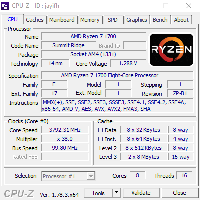
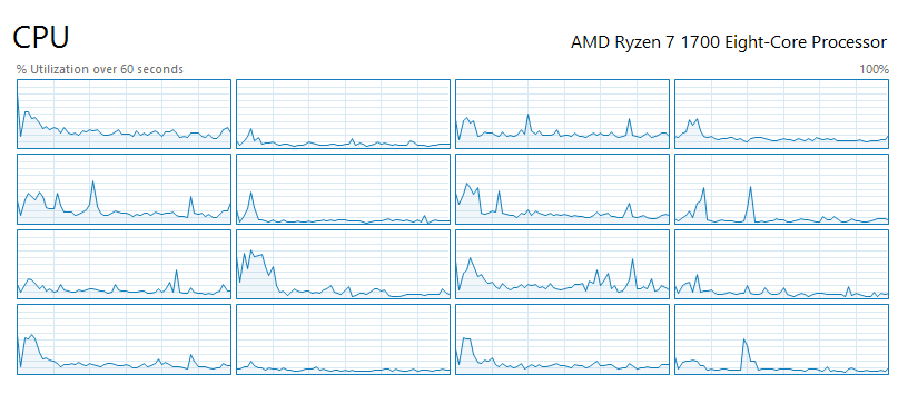
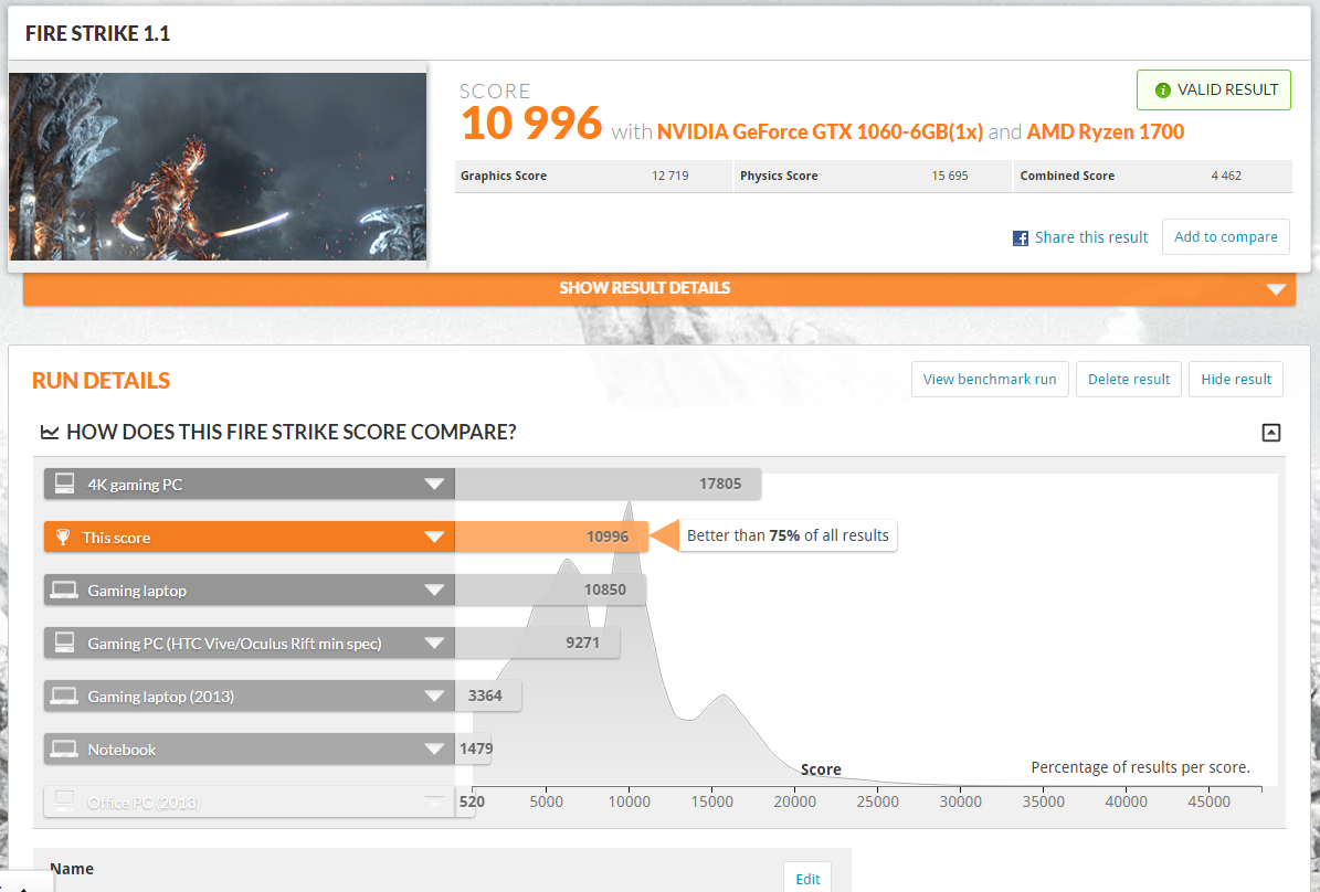
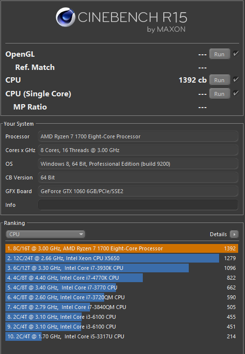
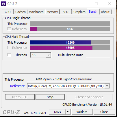
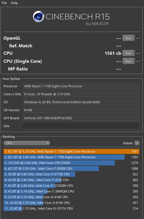
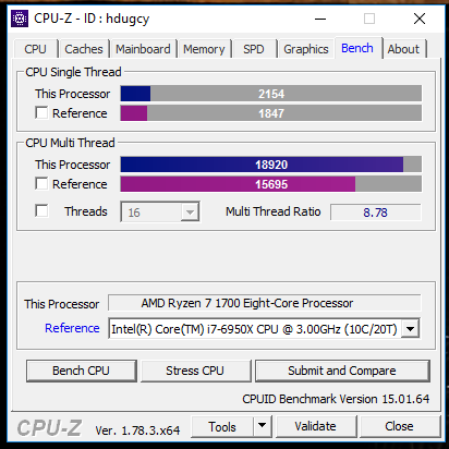
I've simulated the R5 and R3 Ryzen chips by disabling cores 😉  |
|
Deleted
Deleted Member
Join Date: Apr 26, 2024 11:52:39 GMT
Posts: 0
Likes:
Last Online: Apr 26, 2024 11:52:39 GMT
|
Post by Deleted on May 23, 2017 22:37:39 GMT
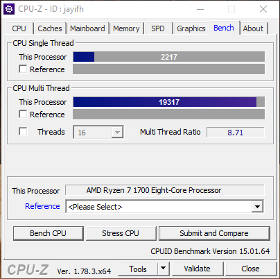
#1 😎🏆  |
|
Deleted
Deleted Member
Join Date: Apr 26, 2024 11:52:39 GMT
Posts: 0
Likes:
Last Online: Apr 26, 2024 11:52:39 GMT
|
Post by Deleted on May 25, 2017 21:16:19 GMT
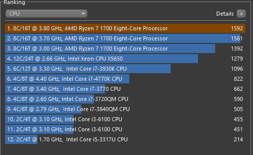
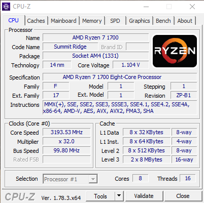
One of the first consumer dual-core CPUs vs a modern 8-core  |
|
Deleted
Deleted Member
Join Date: Apr 26, 2024 11:52:39 GMT
Posts: 0
Likes:
Last Online: Apr 26, 2024 11:52:39 GMT
|
Post by Deleted on May 30, 2017 14:15:55 GMT
The socket on X399 Threadripper motherboards is maaassive 😱😱  |
|
Deleted
Deleted Member
Join Date: Apr 26, 2024 11:52:39 GMT
Posts: 0
Likes:
Last Online: Apr 26, 2024 11:52:39 GMT
|
Post by Deleted on Jun 5, 2017 2:17:31 GMT
Linus has something to say about the new Intel i9 processors and the X299 platform in general... never forget  |
|


 Intel
Intel

 Idles at 40C, load at 75C
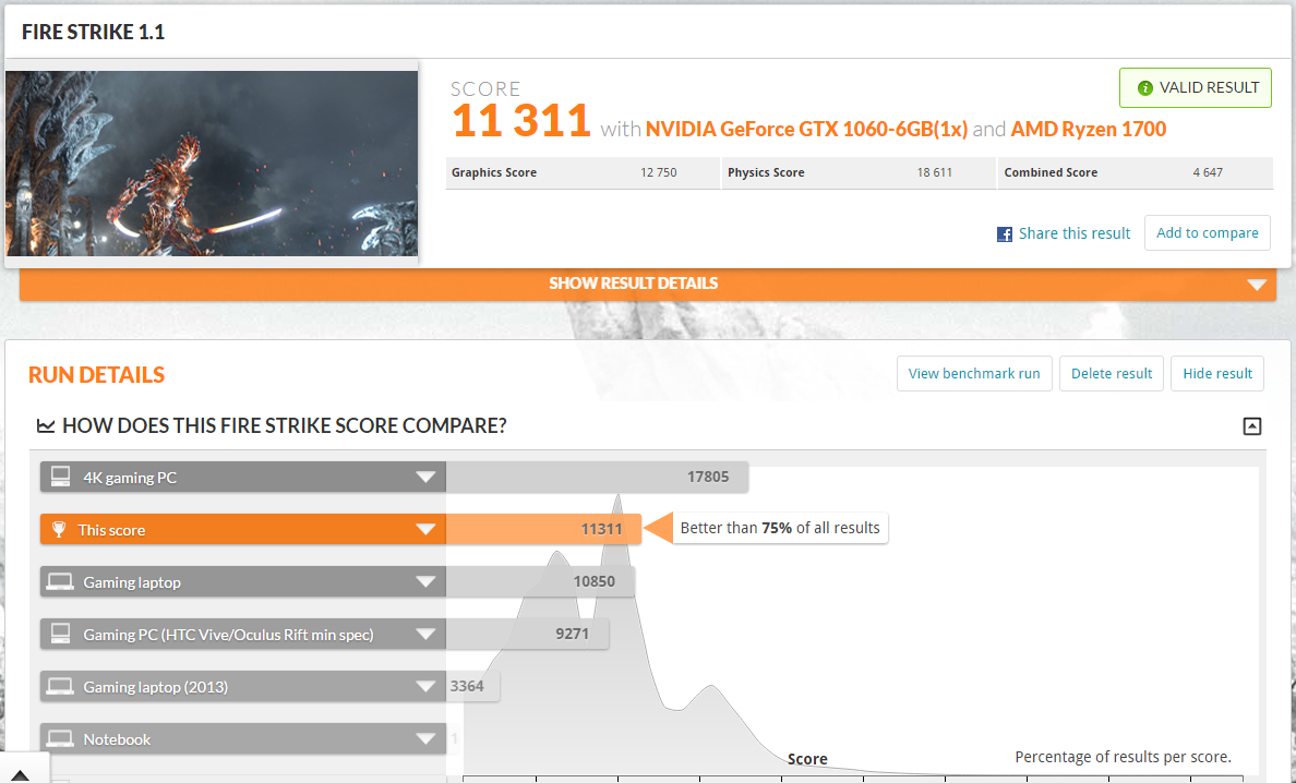
 The code writes into the serial port and there is established connection with my PC on that port (by means of the UART-USB adapter), so my computer can receive the output and show it on the display as you can see. But you probably know what a serial port and terminal connection is.